
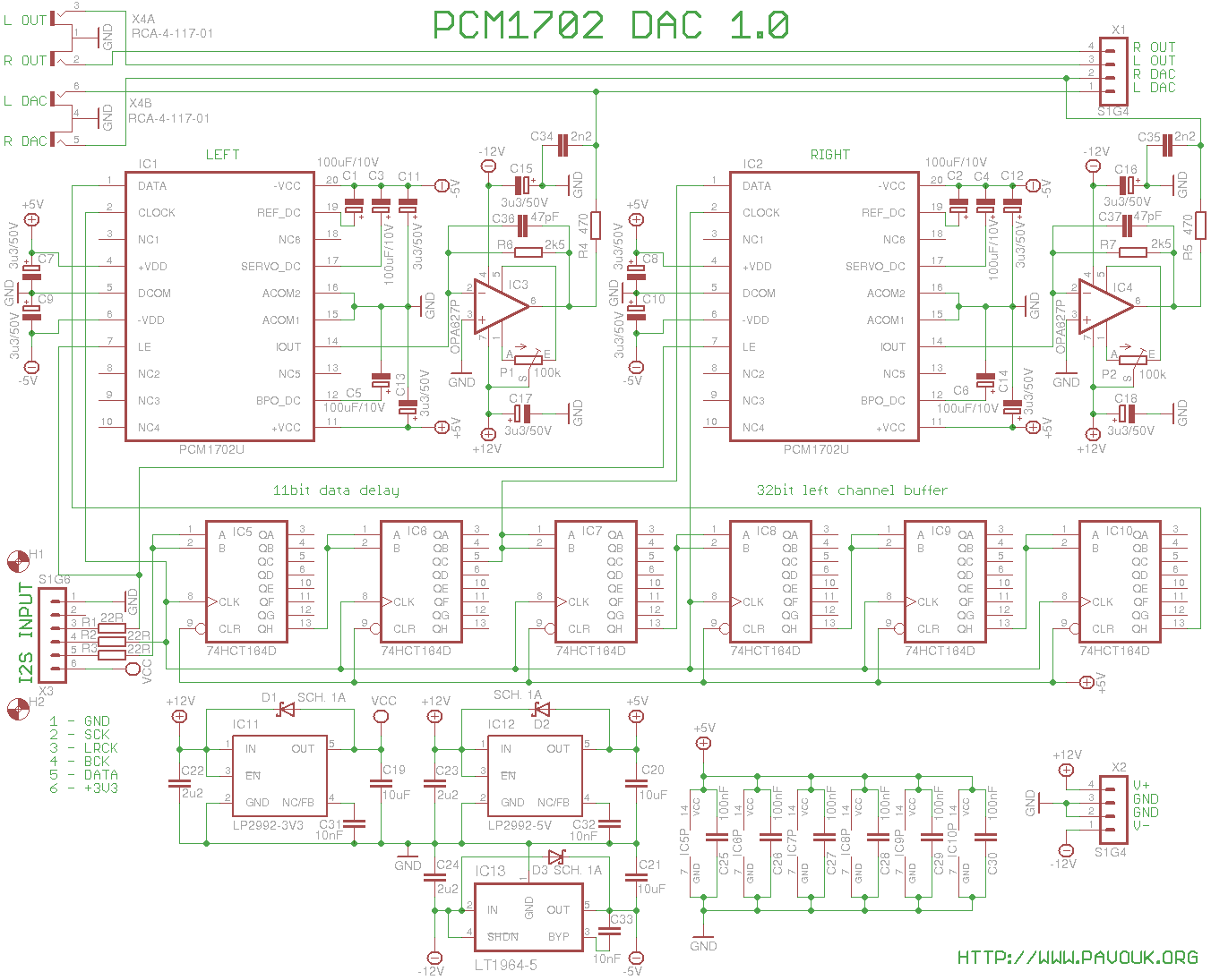
I decided to build DAC with a PCM1702 circuits which are not produced any more but they was available at EBay for a good price. I also had positive experience with a PCM1704 circuits which are very similar but they have 24 bits instead 20 in this DAC. Both are R-2R ladder construction that I expected that they will sound similar to other DACs with this construction and it was confirmed.
Circuit PCM1702 has 20 bits. With a right timing respectively delaying for 11 bits with IC5 and IC6 circuits we reach that 20 most significant bits of sample will be step by step shifted to the DACs shift register and after that with help of LRCK latch signal written on the output. For guarantee that both channels will be played in a same time we must delay left channel data for 32 bits with IC7 to IC10. Thank to this will be data sent to the DACs in a same time. Resistors R1 to R3 are for elimination of signal reflections. IC1 and IC2 are DACs connected similar to datasheet circuit.
For power supply part I used three low-noise voltage regulators. One LP2992-5V for feeding of digital and analog part of DAC and TTL logic circuits. One LT1964-5V for supplying of negative analog part of DAC and one LP2992-3V3 for supplying of input board. PCM1702 works with 5V TTL logic but accept also LVTTL like 74HCT164 that circuit works with I2S input with 3.3V logic. Operational amplifiers are supplied from a main voltage regulators +/-12V.
DAC has current output. For conversion to voltage output I used standard I/V converter circuit with operational amplifier. On the output is simple low-pass filter from R4 and C34, respectively R5 and C35 for second channel. If we want to completely eliminate filter that we replace resistors with zero resistors and we don't assemble capacitors. We can also assemble trimmers P1 and P2 which are for compensation of possible DC offset from operational amplifiers. In my case I had on left channel offset about 2mV and on the right channel about 8mV. We must count with that that when DACs will be without right digital signal because unconnected digital input that on the outputs can be really big DC offset also a few volts. With stopped playing I measured 0.1mV directly on the DACs outputs which is under measure error.
First I assembled voltage regulators IC11 to IC13 and components around them. After that I connected board on the power supply and I checked if output voltages are OK. Next I assembled shift registers IC5 to IC10 and DACs IC1 and IC2 and all rest SMD resistors and capacitors. Next I assembled all electrolytic capacitors from a top side. I was very careful with their right polarity. Next I soldered connectors X1 to X4 and DIL sockets for IC3 and IC4. On the end I screwed distance columns for fixing of input board.
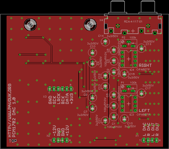
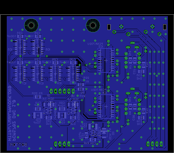
Printed circuit board is designed double-sided. Most of his surface is ground-plane which is on many places connected with a small holes for better shielding. Thickness of a board is ideally 2mm for a good inserting to the Hammond chassis. I used thickness 1.6mm because it was much cheaper. On the sides ground plane absent for isolation from a grounded chassis. I ordered PCB at Seeed Studio company. Required Gerber and Excellon files can be generated in a Free version of Eagle from a materials which are available here.
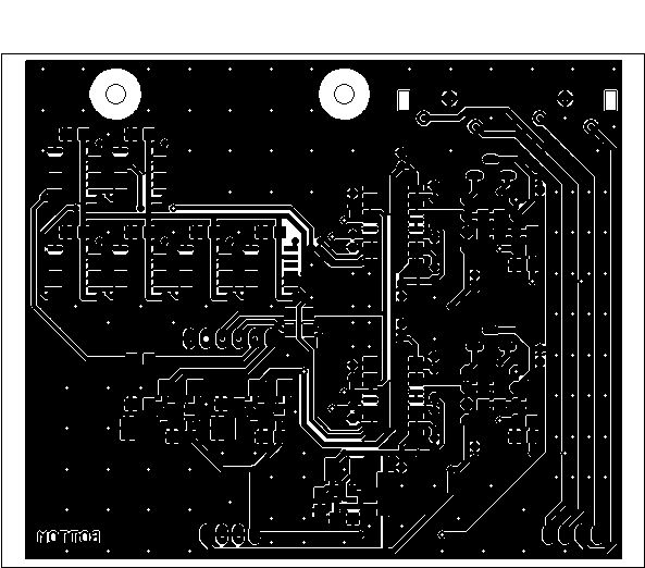
Look on the top side.
 Look on the bottom side.
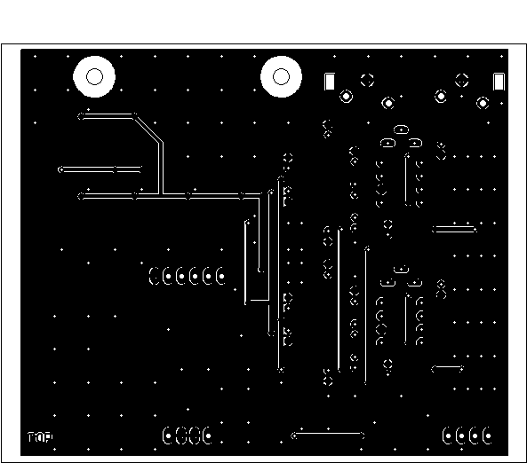
Components can be purchased for example at Farnell company. I could not found foil capacitors C31 to C33 anymore that I replaced them with a ceramic capacitors in a 1206 package. PCM1702 chips I purchased on EBay.
| name | value and type | quantity |
|---|---|---|
| C1-C6 | 100uF/10V electrolytic 105°C RM2 | 6x |
| C7-C18 | 3u3/50V electrolytic 105°C RM2 | 12x |
| C19-C21 | 10uF SMD1206 ceramic | 3x |
| C22-C24 | 2u2 SMD1206 ceramic | 3x |
| C25-C30 | 100nF SMD1206 ceramic | 6x |
| C31-C33 | 10nF SMD1812 foil (1206 ceramic) | 3x |
| C34, C35 | 2n2 SMD1206 ceramic | 2x |
| C36, C37 | 47pF SMD1206 ceramic | 2x |
| D1-D3 | Schottky 1A SMD size B | 3x |
| IC1, IC2 | PCM1702U (U-J, U-K) | 2x |
| IC3, IC4 | OPA627P DIL8 | 2x |
| IC5-IC10 | 74HCT164 SMD SO14 | 6x |
| IC11 | LP2992AIM5-3.3/NOPB SOT23-DBV | 1x |
| IC12 | LP2992AIM5-5/NOPB SOT23-DBV | 1x |
| IC13 | LT1964ES5-5 | 1x |
| P1, P2 | trimmer 100k multiturn 64Y (optional) | 2x |
| R1-R3 | 22R SMD1206 | 3x |
| R4, R5 | 470R SMD1206 | 2x |
| R6, R7 | 2k5 SMD1206 | 2x |
| X1, X2 | Jumper ribbon 90° 4 pins S1G4 | 2x |
| X3 | Jumper ribbon 6 pins 15mm | 1x |
| X4 | Connector cinch 4x socket to the PCB | 1x |
DAC works on the first power-up. His sound is excellent. In comparison with AD1865 is his output level a little lower. Sound is almost identical but is a little sharper. It is also visible on the oscilloscope shape. It is caused by assembled low-pass filter on the output. Difference is really minimal. In comparison with PCM5102 is his sound much better. In a good record is much better locating of instruments and more details. On a bad records we can hear every fail. I tested DAC also on 192kHz/24bit records and it works perfectly. Majority of records I have in a CD quality and they also sounds great.
 English
 Česky
Česky