

Because I wasn't satisfied with behaviour of LME49600 based amplifier specially at power-up I designed headphone amplifier with chip TPA6120A2. Circuit is almost same like amplifier which I designed in a past. I was satisfied with a circuit that I used them again.
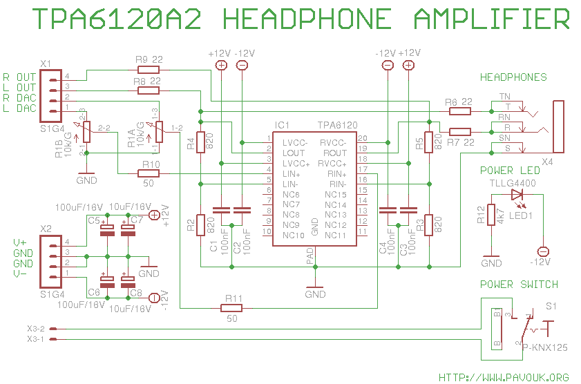
Circuit correspond to recommended datasheet circuit. Unlike past circuit are changed resistors R2 to R5 from a value 1k to 820 ohms for better stability. Input signal goes to the potentiometer R1 and next via resistors R10 and R11 to non-inverting input of amplifier. With resistors R4 and R2 eventually R5 and R3 is connected feedback from amplifier outputs to the inverting inputs. His identical value set the gain to 2. Outputs of amplifier are connected via R6 and R7 for isolation of amplifier from capacitive load and prevent oscillations to the front headphone output. Rear output is connected identically via resistors R8 and R9. Very close to package are placed capacitors C1 to C4 for better stability of amplifier. Around the supply connector are placed tantal electrolytic SMD capacitors C5 to C8 for additional voltage rails filtering.
First I assembled IO1 amplifier circuit. I soldered his two corner opposite pins. Next I rotated board to the top and I soldered a small area with through holes which end directly under center of chip. With capillary effect tin was transported to the second side and solder cooling area of the chip to the board. Next I checked if chip is really good soldered to the board and I soldered rest pins of chip. Next I assembled all SMD resistors and capacitors from smaller to the bigger. Next I mounted connectors X1, X2 and X3. I was careful with their right angle for their good inserting to the neighbour supply board. After this I mounted power supply switch, LED and on the end connector for headphones and potentiometer. I was careful with their position that all components will easily fit in to the front panel. A little more work is only with LED position. We can put board in to the enclosure, fit the LED to the hole and solder it from a upper side.
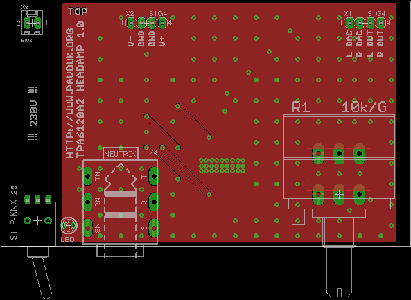
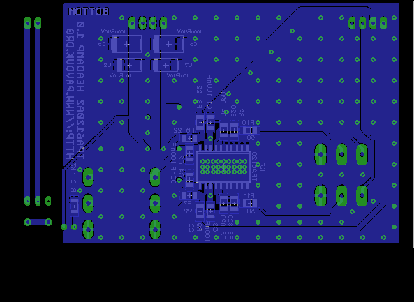
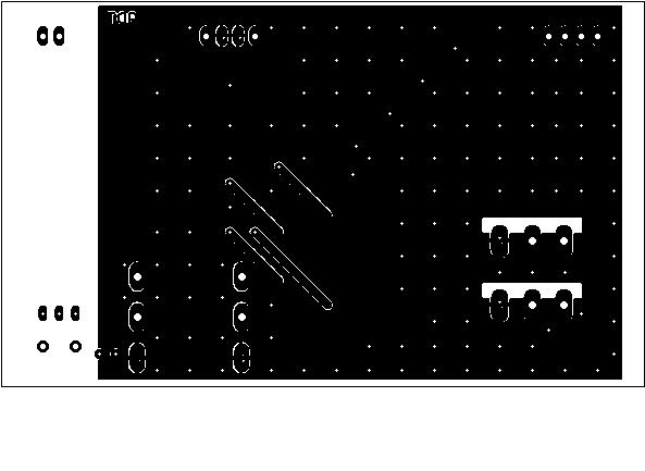
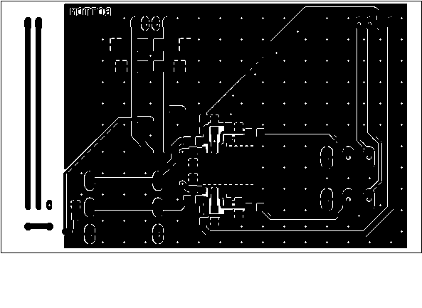
Printed circuit board is designed double-sided. Large piece of surface is used for cooling of chip which is enough and we don't need heatsink. For better shielding and cooling are there many vias. Connections are designed with accent on the star supply lines and good wiring of ground. Components are placed far from power supply board to eliminate interference. Ideal thickness of board is 2mm to precise inserting to the slot in a Hammond chassis. I ordered PCB manufacturing at Seeed Studio. Required Gerber and Excellon files is possible to generate in a Free version of Eagle from a data which are available here.
View to the fully populated opened box.
Top side view.
Bottom side view.
Front panel view.
We can purchase parts for example at Farnell company. I bought potentiometer at SOS Electronic company. Smaller SMD components have size 1206 for easy soldering in amateur conditions.
| name | value and type | quantity |
|---|---|---|
| C1-C4 | 100nF SMD1206 ceramic | 4x |
| C5, C6 | 100uF/25V SMD tantal size D | 2x |
| C7, C8 | 10uF/25V SMD tantal size C | 2x |
| IC1 | TPA6120A2 DWP20 | 1x |
| LED1 | Green 2mm cylinder type | 1x |
| R1 | 10k/G dual potentiometer ALPS-RK27 | 1x |
| R2-R5 | 820R SMD1206 | 4x |
| R6-R9 | 22R SMD1206 | 4x |
| R10, R11 | 50R SMD1206 | 2x |
| R12 | 4k7 SMD1206 | 1x |
| S1 | P-KNX125 | 1x |
| X1, X2 | Jumper ribbon 4 pins S1G4 90° | 2x |
| X3 | Jumper ribbon 2 pins S1G2 90° | 1x |
| X4 | Connector Neutrik NMJ6HCD2 | 1x |
Amplifier sounds great. Without troubles can drive high impedance headphones. Unlike amplifier with LME49600 doesn't make any big punch while power-up or power off. Only slight snap. DC offset is minimal. I measured on the one channel zero and on the second 0.8mV. Board is after a longer time only slightly warm. I am really satisfied with this amplifier. I use rear output for connection of power amplifier Leachamp. Only slight hum from a power supply is noticeable when potentiometer is in the full right position. With normal or higher volume is not anything audible.
-