

This power supply was built like a variant to power supply with Talema transformer. Schematics is same but use Myrra transformer which use UI core. It could guarantee lower magnetic field radiation than EI core similar to toroidal transformer. Unfortunately it was not confirmed and in the analog part of DAC is present hum and noise specially at rear output.
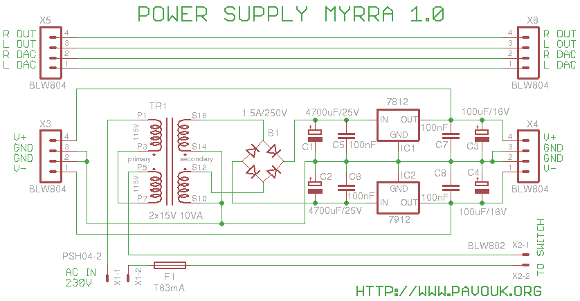
Mains voltage goes to connector X1. One wire goes via fuse F1 and connector X2 on the front board to power switch and back to the transformer TR1. Second wire is connected directly to the primary winding of TR1. Primary side of transformer is connected to 230V. For using on 115V is needed to cut links and put wires on the PCB. Secondary winding is connected to the bridge rectifier B1 and ripple DC voltage is filtered in positive and negative branch by electrolytic capacitors C1 and C2. Very close to the voltage regulators IC1 and IC2 are placed decoupling capacitors C5 to C8 which prevents oscillations and filter higher frequencies. On the outputs of voltage regulators are also filter capacitors C3 and C4. Outputs goes on the connectors X3 and X4 on front and back side of board. GND is doubled for better connection. On the board is also connection of analog signal between front and rear boards.
First I assembled SMD capacitors from a bottom side and also SMD bridge rectifier. We must check right orientation of components. From a top side I assembled other components from a smaller one to bigger. Last I soldered ribbon sockets with accent on the right angle for easy connection of pins from neighbour boards. On the end I screwed small heatsinks on the voltage regulators.
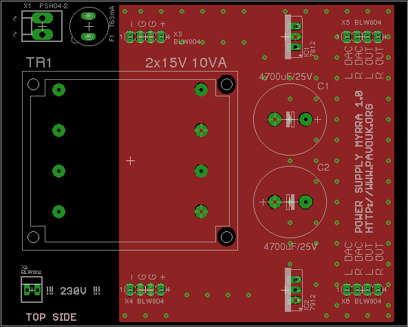
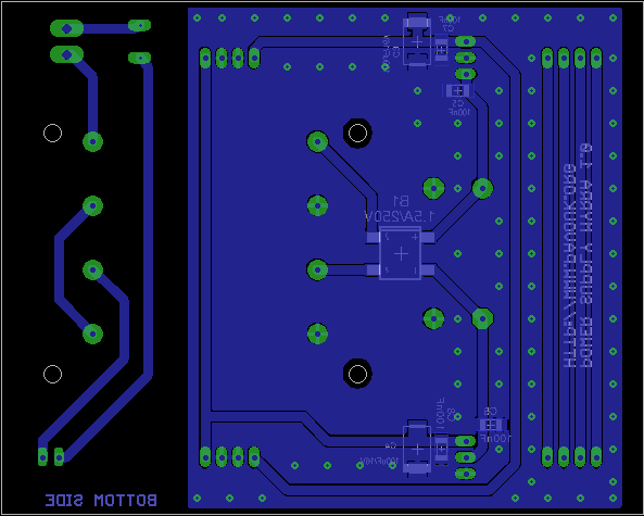
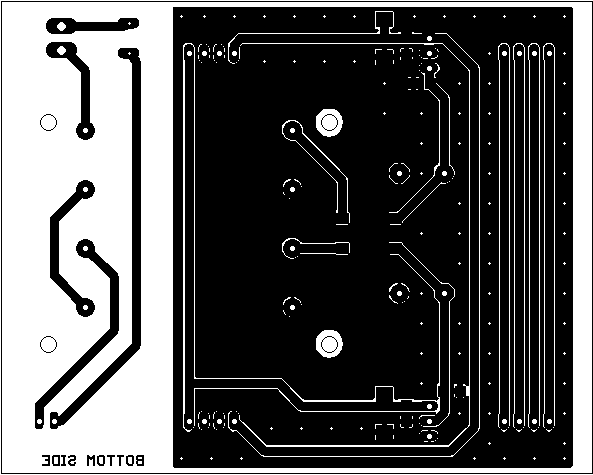
Circuit board is designed double sided. Ground plane is attended for better shield of analog part. Between primary and secondary part is enough isolation space. Sides of board are also isolated to prevent electrical connection with Hammond chassis. I ordered manufacturing of PCB at ELECROW. Required Gerber and Excellon files can be generated in a free version of Eagle from a materials which are here available.
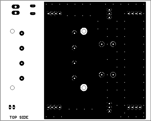
View on the top side.
View on the bottom side.
I purchased transformer from a SOS Electronic company. Big electrolytic capacitors are high-quality types from a Nippon Chemi-Con. They can fit to the chassis very tightly. Other components can be purchased at the common parts shop.
| name | value and type | quantity |
|---|---|---|
| B1 | Bridge rectifier 1.5A/250V SMD DB-S | 1x |
| C1, C2 | 4700uF/25V electrolytic Nippon LXZ RM7.5mm | 2x |
| C3, C4 | 100uF/25V SMD tantal size D | 2x |
| C5-C8 | 100nF SMD1206 ceramic | 4x |
| F1 | Radial fuse T63mA to the PCB | 1x |
| IC1 | 7812 voltage regulator package TO-220 | 1x |
| IC2 | 7912 voltage regulator package TO-220 | 1x |
| TR1 | Transformer MYRRA 2x15V 10VA 45034 | 1x |
| X1 | Connector PSH04-2P 3.96mm | 1x |
| X2 | Ribbon socket 2 pins 90° 10mm | 1x |
| X3-X6 | Ribbon socket 4 pins 90° 10mm | 4x |
Power supply works according to assumption but unfortunately is inducted noise and hum from a transformer to the analog output. Maybe in future I will try to shield transformer but now I recommend to use power supply with a Talema transformer.
-