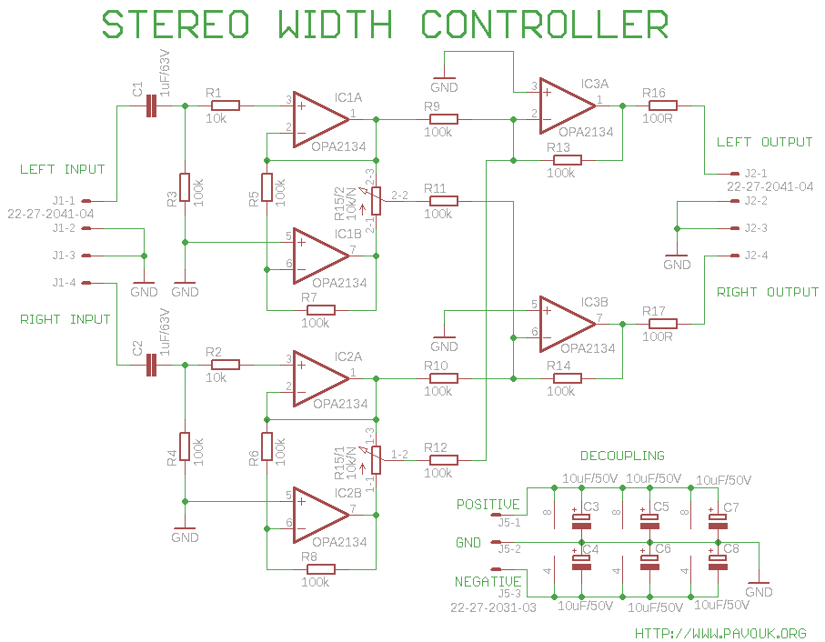
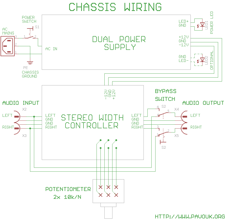
One friend ask me for creating of circuit which allow regulation of stereo width. I doesn't designed circuit by myself because it exists on the internet in more copies for example on Elliott Sound Products page or in Texas Instruments example document. I designed for him printed circuit board and simple dual power supply. Circuit allows on the one side regulation of stereo width to pure mono signal. On the opposite side of regulation we get suppression of signal, which exists in both channels. We can control width of stereophonic base when for example are instruments expanded to a pointless width. Effect is specially audible with headphones where is missing natural mixing of channels in a space around listener and channels are completely isolated. Some records are in this situation unhearable and "pull" the ears. I designed for this circuit simple dual power supply for max. 2x 100mA current.
On the input of circuit is connected operational amplifier IC1A and IC2A in noninverting configuration and on his output is second IC1B and IC2B in inverting configuration. Between their outputs is linear potentiometer whose output is mixed with output of second channel. When the potentiometer is in central position that on his central pin is zero volts and circuit practically doesn't modify final sound. When the potentiometer is in one end position, that on his output is present noninverted output of one channel and is mixed with noninverted output of second channel. With this we get on both output same mixed mono signal. In opposite end position is mixed inverted signal of one channel with noninverted signal of second channel. We get on the output signal, which completely supresses sound which was identical in both channels. This effect is mostly used in karaoke systems where is supressed voice of singer which usually sings in a center of space. Capacitors on the input block eventual DC current and resistors 100R on the output prevents oscillations.
 Chassis wiring in Eagle 6 format
First we check if all holes are correctly drilled. We begin with two wire wraps and all resistors. Next we continue with precise IC sockets for operating amplifiers (if we used them) and next we assemble all capacitors. Beware of polarity! All electrolytic capacitors are oriented in a same direction. On the end we assemble connectors and potentiometer. It can be soldered directly to the board or we can connect them with wires. For connecting of power supply and signal wires is better to use connectors, but we can also solder wires directly to the board. Parts with SMD casing was not used now that soldering of components is much simpler specially for amateurs without experience.
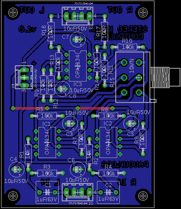
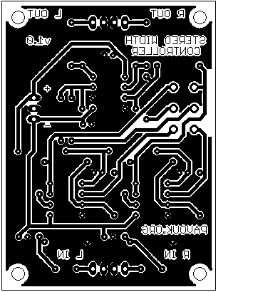
Board is designed single-sided with a big ground area and two wires. It allows to create them in amateur conditions. I ordered it at small local company Kohout Spoj.


Almost all components are usually available. I ordered operational amplifiers OPA2134 at Farnell company. In circuit we can probably use NE5532 which doesn't have too much brilliant parameters but they are much cheaper.
| name | value and type | quantity |
|---|---|---|
| R1, R2 | 10k 1% | 2x |
| R3-R14 | 100k 1% | 12x |
| R15 | dual ganged 10k/N | 1x |
| R16, R17 | 100R | 2x |
| C1, C2 | 1uF/63V foil RM5 | 2x |
| C3-C8 | 10uF/50V electrolytic RM2 | 6x |
| IC1-IC3 | OPA2134 DIL8 | 3x |
| J1-J2 | Molex 4pin PSH02-04P | 2x |
| J3 | Molex 3pin PSH02-03P | 1x |
| Socket IC1-IC3 | Precise socket DIL8 | 3x |
Circuit works according to expectations and produced special sound effects according to potentiometer position. It allow nicely change width of stereophonic base and analyse record mixing. Sound was without hearable distortion and interference.
 English
 Česky
Česky