
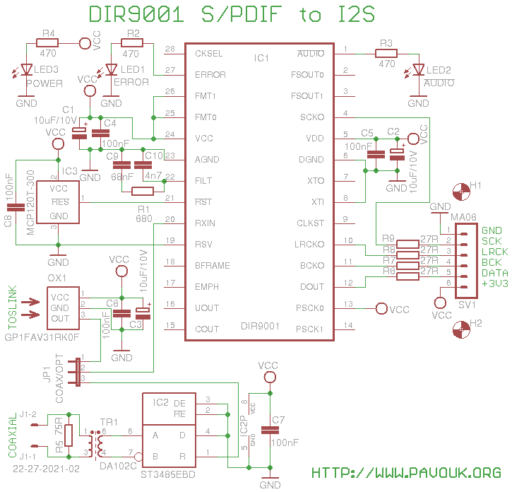
This module works like S/PDIF decoder with I2S output. It uses DIR9001 circuit which works up to 96kHz sample frequency. Module has optical and electrically isolated coaxial input. On the board it is possible to mount only optical connector. When we want to use electrical input that we don't mount optical connector and we mount cinch connector directly to the hole in the back side and connect it with a wire to the input on the board.
Board is powered from a 3.3V voltage regulator which is on the DAC board. Circuit has on his power pins filter capacitors C1 and C2 and decoupling capacitors C4 and C5. Optical input use optical receiver OX1 from a Sharp company which has TTL compatible output which is connected via jumper JP1 directly to the IC1. On the power pins of optical receiver are capacitors C3 and C6. Electrical input J1 is connected via resistor R5 which guarantee a right input impedance to the pulse transformer TR1. It provides electrical isolation of input for prevention of ground loop. Output from a transformer goes to the RS485 receiver IC2. It is permanently switched to the input mode and accept differential input voltage in a range from 0.2V to 14V. His output is TTL compatible and again goes to the JP1 switch. Correct reset of IC1 after power-up is guaranteed by IC3 circuit. Circuit IC1 is permanently preconfigured for I2S output data format with pins FMT0 and FMT1. SCK output is preconfigured to 256xFS frequency with PSCK0 and PSCK1 pins. On the board are soldered two SMD LEDs. Green LED3 show presence of power supply voltage. Yellow LED2 light only when S/PDIF signal is present and doesn't contain PCM audio data. Red LED1 light when S/PDIF signal is not present or error is detected. This LED is in the hole on the back panel. I2S bus output signals goes to the connector SV1 via resistors R6 to R9 which guarantee impedance match and prevent signal reflection on the wires.
First I assembled circuit IC1. I soldered his two outer pins on one side. I applied liquid colophony on a both sides of chip and I soldered completely second side of chip. Next I soldered completely first side. With a similar way I soldered IC2 and IC3. Next I soldered all SMD resistors, capacitors and LEDs. Next I soldered all conectors and transformer. LED1 must be installed to the existing hole in a back panel and after right positioning soldered. When we don't want to use electrical input that it is not needed to mount IC2, C7, TR1, R5 and J1. When we don't want to use optical input that we don't mount OX1, C3 and C6. From a optical receiver is needed to cut a upper part with a hole for screw to fit a receiver between boards. It reduce mechanical firmness but I hope that it will be OK.
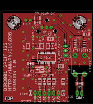
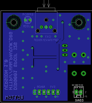
PCB is designed double-sided and it fit to 5x5cm dimensions for cheaper manufacturing. Majority of components are from a top side. From a bottom side are all connectors and LED1. I ordered manufacturing of PCB at ELECROW company. Required Gerber and Excellon files can be generated in a Free version of Eagle from a materials which are available here.
Top side view
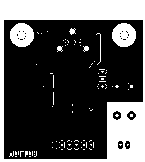
Bottom side view

Circuit DIR9001 and transformer DA102C I purchased at Farnell company. Rest parts I purchased at local shop with electronic parts GM Electronic.
| name | value and type | quantity |
|---|---|---|
| C1-C3 | 10uF/10V tantal SMD size B | 3x |
| C4-C8 | 100nF SMD1206 ceramic | 5x |
| C9 | 68nF SMD1206 ceramic | 1x |
| C10 | 4n7 SMD1206 ceramic | 1x |
| IC1 | DIR9001 | 1x |
| IC2 | ST3485EBD SO-08 | 1x |
| IC3 | MCP120T-300 SOT23 | 1x |
| J1 | Connector PSH02-02WG 2pin 90° | 1x |
| JP1 | Jumper pin S1G3 2.54mm 3 pins | 1x |
| LED1 | LED red 2mm cylindrical | 1x |
| LED2 | LED yellow SMD1206 | 1x |
| LED3 | LED green SMD1206 | 1x |
| OX1 | GP1FAV31RK0F | 1x |
| R1 | 680R SMD1206 | 1x |
| R2-R4 | 470R SMD1206 | 3x |
| R5 | 75R SMD1206 | 1x |
| R6-R9 | 27R SMD1206 | 4x |
| SV1 | Ribbon socket 6 pins 10mm | 1x |
| TR1 | DA102C or PE-65612 or S22083 | 1x |
After power-up I found that power LED don't light. After few minutes of searching short circuit I discovered that doesn't work power cord. It was almost new but too thin and light. I throwed it up to the garbage and replaced them with a cable from a power supply for old notebook. After this power LED lights up but also ERROR LED shine and don't want to turn off. After some time I discovered that S/PDIF signal from my computer simply doesn't go out. I took my USB soundcard which has also electrical and optical S/PDIF output and I connected it to the input. Now LED ERROR turned off and DAC begin to play music. I tried also optical input and it works also OK. Circuit works great and it is suitable for those who want to build my modular audio system with S/PDIF input.
-
 English
 Česky
Česky