
For many years I wanted to make a USB soundcard which will support sampling 192kHz/24bit. Now are manufactured simple chips which looks like a soundcard on USB bus. For example PCM2706. Unfortunately it supports maximum sampling 48kHz/16bit. Next option was Tenor TE7022 chip which support only up to 96kHz and it is obsolete and his documentation is not freely available. Next often used solution is with XMOS processor. Example is top-class WaveIO module which support up to 384kHz. Next great USB-I2S converter is called Amanero and use processor ATSAM3U1CA. My project is based on Audio-Widget project which is part of SDR-Widget project. It uses identical circuit with a small changes to keep compatibility with a original firmware. Software support both UAC (USB Audio Class) modes 1 and 2. Mode UAC1 is needed for Windows because they normally doesn't support higher sample frequencies. For them is needed special USB audio driver to support UAC2 features. In Linux and Mac is not problem with UAC2 support.
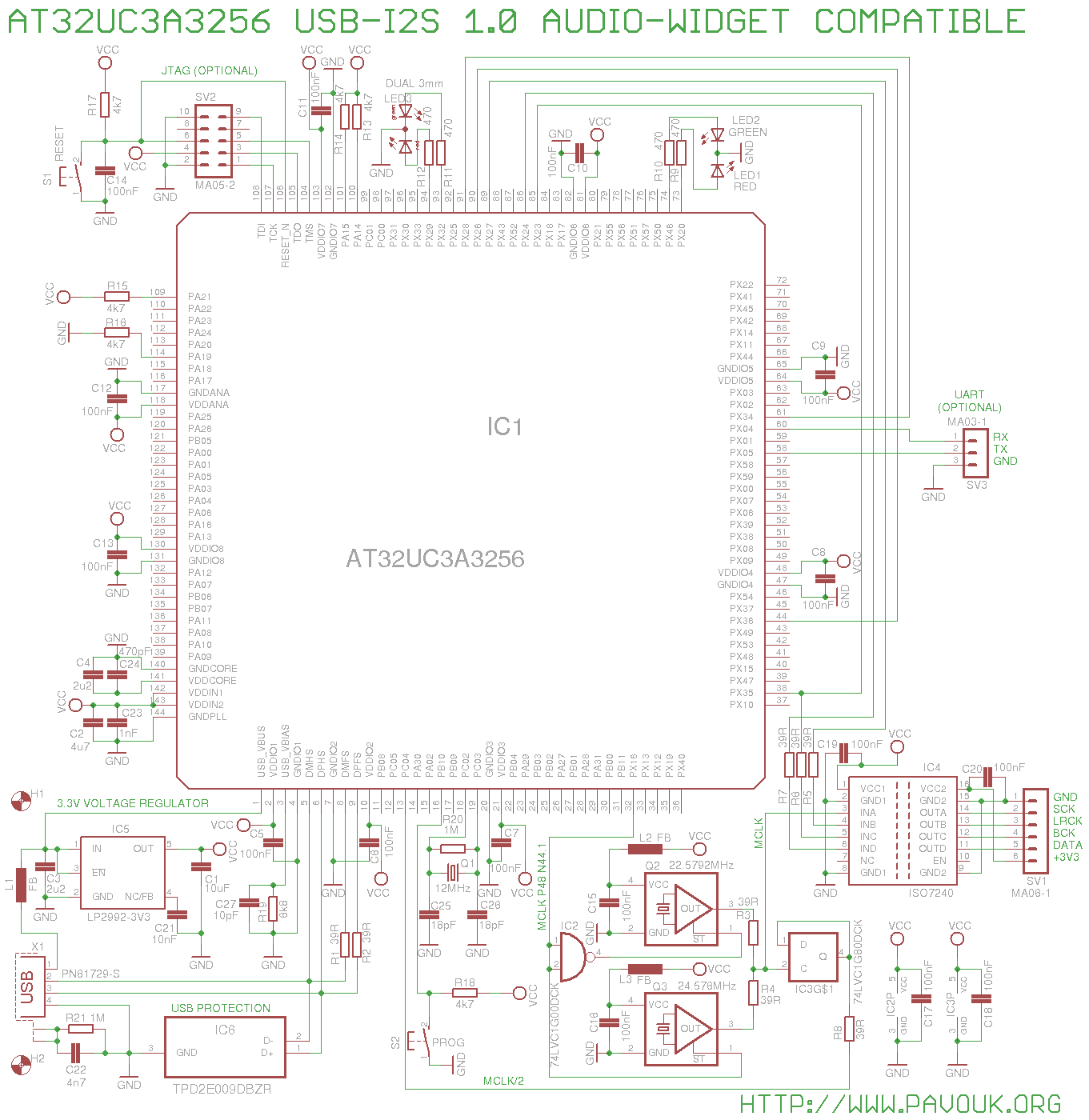
Processor AT32UC3A3256 is connected to the USB bus. It supports both full-speed and high-speed modes on individual pins. On the USB data pins is also connected ESD protection part which protect processor from voltage peaks. Processor and all other parts are powered from 3.3V voltage regulator IC5. On all power pins are connected decoupling capacitors. Quartz oscillators have additional ferrite beads on the power lines. Quartz oscillators Q2 and Q3 are used for generating of precise MCLK frequency for DAC on the main board. Via divider by two IC3 goes signal back to the processor for synchronization of BCK, DATA and LRCK signals. Because processor use on the USB bus asynchronous mode, that generated frequency to the DAC is very precise and with minimum jitter. Processor itself tells to the computer if he must slow down or send data faster. Processor also with pin 32 switch which oscillator is active. Oscillator Q2 is used for multiple of 44.1kHz sample frequency and Q3 for multiple of 48kHz. All signals for DAC goes to the isolator IC4 which them electrically isolate from rest of DAC. His secondary side is powered from DAC board. There is also pins for JTAG connector for potential programming when we destroy internal bootloader. For debugging is there also one UART which can be via voltage converter connected to the RS232 serial port. On the board are also two SMD LEDs which signalling while playing requests for acceleration (LED2) or slowing down (LED1) of data transfer. On the back panel is places two-coloured LED3 which light green in UAC1 mode and red in UAC2. For configuration and programming are there small buttons PROG and RESET.
Assembling of this board was nightmare. Main processor has 144 pins and unfortunately they are really near. I begun with them because I wanted to have around a much space. I soldered two opposite corner pins. Next I put enough of gel colophony and on the soldering Iron I get a piece of tin and I run over all pins on one side of chip. It doesn't look bad, but few pins connected together. I used popular solder wick but with a horror I recognized that it almost doesn't work. Pins are too close that capillary effect of wick refuse work. On the end I used method of warm-up and beat to the table. On the other sides of chip I was much more careful. I used less of tin and I tried to not connect neighbour pins.
Next I tried to solder quartz and oscillators. It was another nightmare :-) Parts have ceramic package and pins in a corners from a bottom. It get some time when I discovered that on the sides in a corners are very small pieces of bottom pins and when I move closer with a soldering iron that it suck tin under package with a capillary effect. It was even worse to solder oscillators because I found on the market only pieces with a size 2.5x2mm which is really small package. I succesfully soldered them with a same procedure but it is on the border of possibility. Pin 1 is marked with a angled edge. Next I soldered voltage regulators and other SMD parts from a top side of board. In comparison to previous experience was soldering of SMD parts with 0603 size piece of cake. After assembling of all SMD parts from a top side I continued from a bottom side of board. On the end I placed connectors. I was careful for side in which is connector mounted.
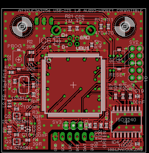
I succesfully designed double-sided board with a size 5x5cm. It is required to use SMD parts with a 0603 size. Components are mounted from a both sides. I tried to distribute components that they can be easily soldered. There was not much space for a names, values and descriptions but on the end it was not bad. I ordered manufacturing of PCB at Seeed Studio company. Required Gerber and Excellon files can be generated in a Free version of Eagle from a materials which are available here.
Top side view.
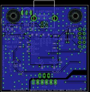
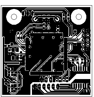
Bottom side view.

Parts can be purchased for example at Farnell company. Most problematic parts are oscillators which I found only in 2.5x2mm package.
| name | value and type | quantity |
|---|---|---|
| C1 | 10uF SMD0603 ceramic | 1x |
| C2 | 4u7 SMD0603 ceramic | 1x |
| C3, C4 | 2u2 SMD0603 ceramic | 2x |
| C5-C20 | 100nF SMD0603 ceramic | 16x |
| C21 | 10nF SMD0603 ceramic | 1x |
| C22 | 4n7 SMD0603 ceramic | 1x |
| C23 | 1nF SMD0603 ceramic | 1x |
| C24 | 470pF SMD0603 ceramic | 1x |
| C25, C26 | 18pF SMD0603 ceramic | 2x |
| C27 | 10pF SMD0603 ceramic | 1x |
| IC1 | AT32UC3A3256 LQFP144 | 1x |
| IC2 | 74LVC1G00DCK SC70-5 | 1x |
| IC3 | 74LVC1G80DCK SC70-5 | 1x |
| IC4 | ISO7240C | 1x |
| IC5 | LP2992AIM5-3.3/NOPB SOT23-DBV | 1x |
| IC6 | TPD2E009DBZR SOT-23 | 1x |
| L1-L3 | Ferrite bead 0.03ohm 3A SMD0805 | 3x |
| LED1 | LED red SMD0603 | 1x |
| LED2 | LED green SMD0603 | 1x |
| LED3 | LED two-coloured 2-3mm | 1x |
| Q1 | Quartz 12MHz SMD 6x3.5mm (ABRACON ABMM2) | 1x |
| Q2 | Oscillator 22.5792MHz SMD 2.5x2mm (EPSON SG-210STF) | 1x |
| Q3 | Oscillator 24.576MHz SMD 2.5x2mm (EPSON SG-210STF) | 1x |
| R1-R8 | 39R SMD0603 | 8x |
| R9-R12 | 470 SMD0603 | 4x |
| R13-R18 | 4k7 SMD0603 | 6x |
| R19 | 6k8 SMD0603 | 1x |
| R20, R21 | 1M SMD0603 | 2x |
| S1, S2 | SMD switch KSR221G | 2x |
| SV1 | Ribbon socket 6 pins 10mm | 1x |
| SV2 | Jumper ribbon 2x5 pins | 1x |
| SV3 | Jumper ribbon 1x3 pins | 1x |
| X1 | USB type B to DPS 90° | 1x |
Because I am not programmer that I used finished binary firmware. I used firmware Audio-Widget Henry Audio USB DAC 128 mkII or also QNKTC AB-1.2. Because same circuit exists minimum in 10 variants that there also exists many variants of firmware. I used probably most recent version of firmware.
Most of important information for running of module is available in this original document: AW_readme.txt. I describe only shortly how I made firmware upgrade under Linux:
# Add support AT32UC3A3256
SUBSYSTEM=="usb", ENV{DEVTYPE}=="usb", ATTRS{idVendor}=="03eb",
ATTRS{idProduct}=="2ff1", MODE:="0666"
[ 5577.057130] usb 1-2.2: new full-speed USB device number 4 using ehci-pci
[ 5577.133868] usb 1-2.2: New USB device found, idVendor=03eb, idProduct=2ff1
[ 5577.133876] usb 1-2.2: New USB device strings: Mfr=1, Product=2, SerialNumber=3
[ 5577.133882] usb 1-2.2: Product: AT32UC3A DFU
[ 5577.133888] usb 1-2.2: Manufacturer: ATMEL
[ 5577.133893] usb 1-2.2: SerialNumber: 1.0.3
In lsusb we can see this:
Bus 001 Device 004: ID 03eb:2ff1 Atmel Corp.
When chip was already programmed in past that we can recall internal bootloader with press of PROG button and next with press and release of RESET button and in the end release of PROG button.
[pavouk@home audiowidget]$ ./program-widget awx_20140918_mkII_RC03.elf
program-widget with awx_20140918_mkII_RC03.elf
     target: at32uc3a3256
    chip_id: 0x2ff1
  vendor_id: 0x03eb
    command: erase
      quiet: false
      debug: 6
device_type: AVR32
------ command specific below ------
   validate: true

     target: at32uc3a3256
    chip_id: 0x2ff1
  vendor_id: 0x03eb
    command: flash
      quiet: false
      debug: 6
device_type: AVR32
------ command specific below ------
   validate: true
   hex file: /tmp/awx_20140918_mkII_RC03.hex

Validating...
117024 bytes used (46.08%)
     target: at32uc3a3256
    chip_id: 0x2ff1
  vendor_id: 0x03eb
    command: reset
      quiet: false
      debug: 4
device_type: AVR32
------ command specific below ------
[ 6253.845114] usb 1-2.2: new high-speed USB device number 5 using ehci-pci
[ 6253.920489] usb 1-2.2: New USB device found, idVendor=16d0, idProduct=075d
[ 6253.920501] usb 1-2.2: New USB device strings: Mfr=1, Product=2, SerialNumber=3
[ 6253.920508] usb 1-2.2: Product: Henry Audio USB DAC 128 mkII
[ 6253.920514] usb 1-2.2: Manufacturer: Audio-Widget
[ 6253.920519] usb 1-2.2: SerialNumber: 2014091800BSB
[ 6253.929288] input: Audio-Widget Henry Audio USB DAC 128 mkII as /devices/pci0000:00/0000:00:13.5/usb1/1-2/1-2.2/1-2.2:1.3/0003:16D0:075D.0002/input/input9
[ 6253.929634] hid-generic 0003:16D0:075D.0002: input,hidraw0: USB HID v1.11 Device [Audio-Widget Henry Audio USB DAC 128 mkII] on usb-0000:00:13.5-2.2/input3
In lsusb I see this:
Bus 001 Device 005: ID 16d0:075d MCS AB-1.x UAC2 [Audio Widget]
Now is USB-I2S converter registered in a system like a USB soundcard in UAC2 mode.
Module has only two push buttons. By a pushing of RESET we reset circuit.
When we hold a button PROG for about 10 seconds until back LED turn off unit will be switched to opposite UAC mode and after push RESET button will be circuit resetted and registered in a new mode. Processor will write settings in to the internal non-volatile memory and after next connection it is registered always in a same mode. In my case looks DMESG that:
[ 1106.752943] usb 1-2.2: USB disconnect, device number 3
[ 1107.444194] usb 1-2.2: new full-speed USB device number 4 using ehci-pci
[ 1107.526434] usb 1-2.2: New USB device found, idVendor=16d0, idProduct=075c
[ 1107.526443] usb 1-2.2: New USB device strings: Mfr=1, Product=2, SerialNumber=3
[ 1107.526449] usb 1-2.2: Product: Henry Audio USB DAC 128 mkII
[ 1107.526455] usb 1-2.2: Manufacturer: Audio-Widget
[ 1107.526459] usb 1-2.2: SerialNumber: 2014091800BSB
[ 1107.533491] input: Audio-Widget Henry Audio USB DAC 128 mkII as /devices/pci0000:00/0000:00:13.5/usb1/1-2/1-2.2/1-2.2:1.1/0003:16D0:075C.0002/input/input9
[ 1107.533840] hid-generic 0003:16D0:075C.0002: input,hidraw0: USB HID v1.11 Device [Audio-Widget Henry Audio USB DAC 128 mkII] on usb-0000:00:13.5-2.2/input1
[ 1107.549307] ALSA sound/usb/mixer.c:936 18:2: cannot get min/max values for control 2 (id 18)
[ 1107.661315] ALSA sound/usb/mixer.c:936 18:2: cannot get min/max values for control 2 (id 18)
[ 1107.671331] ALSA sound/usb/mixer.c:936 18:2: cannot get min/max values for control 2 (id 18)
[ 1107.681313] ALSA sound/usb/mixer.c:936 18:2: cannot get min/max values for control 2 (id 18)
[ 1107.691317] ALSA sound/usb/mixer.c:936 18:2: cannot get min/max values for control 2 (id 18)
[ 1107.701326] ALSA sound/usb/mixer.c:936 18:2: cannot get min/max values for control 2 (id 18)
[ 1107.711319] ALSA sound/usb/mixer.c:936 18:2: cannot get min/max values for control 2 (id 18)
[ 1107.721317] ALSA sound/usb/mixer.c:936 18:2: cannot get min/max values for control 2 (id 18)
[ 1107.731319] ALSA sound/usb/mixer.c:936 18:2: cannot get min/max values for control 2 (id 18)
[ 1107.741324] ALSA sound/usb/mixer.c:936 18:2: cannot get min/max values for control 2 (id 18)
[ 1107.751312] ALSA sound/usb/mixer.c:417 cannot get current value for control 2 ch 1: err = -22
[ 1107.769321] ALSA sound/usb/mixer.c:417 cannot get current value for control 2 ch 1: err = -22
[ 1107.780329] ALSA sound/usb/mixer.c:417 cannot get current value for control 1 ch 0: err = -22
[ 1107.810456] ALSA sound/usb/mixer.c:417 cannot get current value for control 1 ch 0: err = -22
[ 1107.946462] ALSA sound/usb/mixer.c:417 cannot get current value for control 1 ch 0: err = -22
[ 1108.064485] ALSA sound/usb/mixer.c:417 cannot get current value for control 1 ch 0: err = -22
In lsusb we can see this:
Bus 001 Device 004: ID 16d0:075c MCS AB-1.x UAC1 [Audio Widget]
There are visible some errors which could be caused by error in firmware or in Linux kernel. I didn't look deeper on it now.
Features of the module can be controlled also by software. There exists 3 versions of program Widget Control. Version for Windows and two versions for Linux in Python and C.
I downloaded source code widget-control.c. It is also needed file src/features.h. I put them in a created src directory. it is also needed to have installed developer package libusb-devel. Next I executed:
gcc -o widget-control widget-control.c -lusb-1.0
When everything is OK that there appears binary file widget-control. Now we must only set execute rights.
With this command we list all connected converters which program found:
[root@home audiowidget]# ./widget-control -a
16d0:075d 2014091800BSB
List of features from nvram:
[root@home audiowidget]# ./widget-control -g
12 44 usbi2s uac2_audio normal normal none generic hd44780 500ms fir quirk_none
Command for reconfiguration to the UAC1 mode:
./widget-control -s 12 44 usbi2s uac1_audio normal normal none generic hd44780 500ms fir quirk_none
Command for reconfiguration to the UAC2 mode:
./widget-control -s 12 44 usbi2s uac2_audio normal normal none generic hd44780 500ms fir quirk_none
Command for reset:
./widget-control -r
For Linux and Mac are not needed any drivers for full use of module, because they are part of system core. Windows includes only support for UAC1 mode and for full use is needed to download drivers from original pages. It is needed to get right driver which will know exact card ID according to used firmware.
In Linux I hit the troubles that in Alsa mode doesn't work playing in XMMS application. When I use OSS emulation that it works perfectly in UAC2 mode. In other players I didn't see this problem and with another USB-I2S converter XMMS works correctly. In UAC1 mode is situation a little worse. In OSS mode it plays incorrectly. Music jumps and tears. I can't tell if problem is in firmware, in player or in a kernel driver.
Output when playing CD record:
[root@home audiowidget]# cat /proc/asound/card2/stream0
Audio-Widget Henry Audio USB DAC 128 mkII at usb-0000:00:13.5-2.2, high speed : USB Audio

Playback:
  Status: Running
    Interface = 2
    Altset = 1
    Packet Size = 126
    Momentary freq = 44100 Hz (0x5.8333)
    Feedback Format = 15.17
  Interface 2
    Altset 1
    Format: S32_LE
    Channels: 2
    Endpoint: 2 OUT (ASYNC)
    Rates: 44100, 88200, 132300, 176400, 48000, 96000, 144000, 192000
    Data packet interval: 250 us
Output when playing 192kHz/24bit record:
[root@home audiowidget]# cat /proc/asound/card2/stream0
Audio-Widget Henry Audio USB DAC 128 mkII at usb-0000:00:13.5-2.2, high speed : USB Audio

Playback:
  Status: Running
    Interface = 2
    Altset = 1
    Packet Size = 392
    Momentary freq = 192000 Hz (0x18.0000)
    Feedback Format = 15.17
  Interface 2
    Altset 1
    Format: S32_LE
    Channels: 2
    Endpoint: 2 OUT (ASYNC)
    Rates: 44100, 88200, 132300, 176400, 48000, 96000, 144000, 192000
    Data packet interval: 250 us
From a outputs we can see that player switches sample frequency and data transfer is asynchronous. Some players make resampling to the 48kHz. For sure I checked it directly on the clock signals with a oscilloscope.
With this project I was not sure with a result because original circuit is known but connection of oscillators is made differently. Oscillators was part of DAC but I placed them near processor. Original schematics was for me chaotic. Also design of PCB was very complicated. I had goal PCB size 5x5cm which I meet it but I had to use smaller parts which complicates assembling. After first power-up processor appear on a USB bus but after mechanical stress dissapear. I had to careful resolder all pins of processor and remove all possible cold junctions. I was succesful that board now works reliable. I didn't like software troubles with playing and errors from kernel in UAC1 mode. I will look on it later after reinstallation of my system which I have on schedule. I am lucky that I succesfully realised this project. Thanks to this I succesfully tested DAC boards up to 192kHz/24bit. I want to thanks to all original authors of SDR-Widget and Audio-Widget project for their great work which allow me to realize my project.
 English
 Česky
Česky