My friend ask me for creating of printed circuit board for a guitar booster. It is not my construction but circuit is from some old journal Amaterske radio. Unfortunately I didn't know author of this construction. Original circuit use germanium and silicon transistors from TESLA production. Circuit is designed for built-in to the guitar.
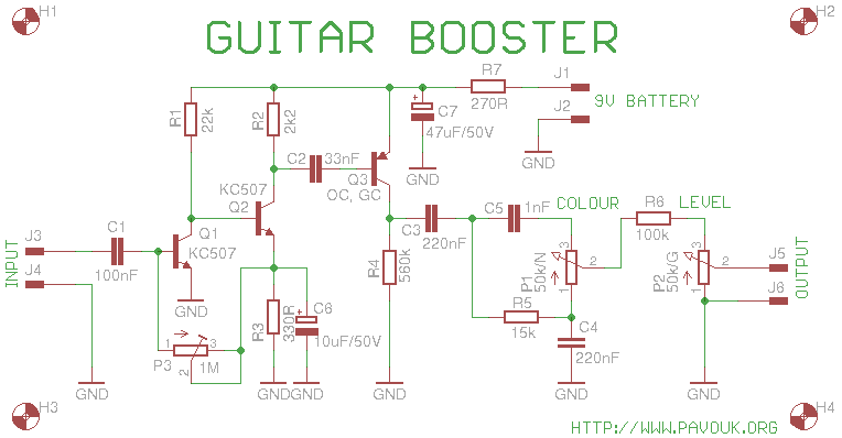 Booster schematics in Eagle 7 format
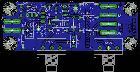
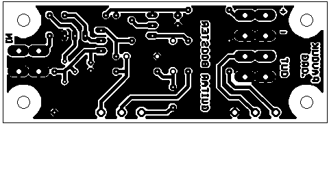
Printed circuit board is single-sided without any wire-wrap. It can be created in amateur condition, but if is not used solder-mask, that soldering of wires is a little complicated around ground planes.
Transistors KC507 can be replaced with BC546. With a replacement of germanium transistor OC or GC I am not sure if will be satisfying silicon transistor BC556. Other components are commonly available.
| name | value and type | quantity |
|---|---|---|
| P1 | 50k/N linear potentiometer | 1x |
| P2 | 50k/G logarithmic potentiometer | 1x |
| P3 | 1M trimmer type 64Y | 1x |
| R1 | 22k | 1x |
| R2 | 2k2 | 1x |
| R3 | 330 | 1x |
| R4 | 560k | 1x |
| R5 | 15k | 1x |
| R6 | 100k | 1x |
| R7 | 270 | 1x |
| C1 | 100nF/63V foil RM5 | 1x |
| C2 | 33nF/63V foil RM5 | 1x |
| C3, C4 | 220nF/63V foil RM7.5 | 2x |
| C5 | 1nF/63V foil RM5 | 1x |
| C6 | 10uF/50V electrolytic RM2 | 1x |
| C7 | 47uF/50V electrolytic RM2.5 | 1x |
| Q1, Q2 | KC507 or similar (BC546) silicone transistor | 2x |
| Q3 | OC..., GC... germanium transistor | 1x |
| J1-J6 | Faston in to the PCB | 6x |
Until now I haven't information how circuit works.
 English
 Česky
Česky