
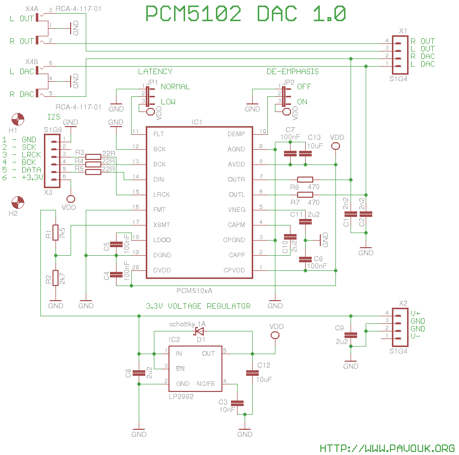
I decidec to build DAC with PCM5102 like a first DAC for testing of modular concept. This DAC support sample frequency up to 384kHz it can generate SCK clock signal and negative voltage by itself and includes line-out drivers. It is classic oversampling delta-sigma DAC with all his bad attributes.
From the input board goes I2S bus signals via X3 connector to the converter. On the wires are placed R3 to R5 resistors for preventing of reflection of signal on the end of line. From the DAC IC1 goes analog outputs via low-pass filter to the pair of cinch connectors X4 on the backside and to the connector X1 for connection of headphone amplifier. Output filter has -3dB filter point approximately at 153kHz. It is compounded from a R6, C1 and R7, C2. On all supply pins of the DAC are decoupling capacitors.
On the XSMT pin of IC1 is connected voltage divider R1, R2 which measure voltage on the input of voltage regulator and if it is lower than about 8 volts that analog output of DAC is muted.
For feeding of DAC I selected low-noise voltage regulator LP2992. On the input and on the output of voltage regulator are placed decoupling capacitors C8 and C12 which provides a good circuit stability. To the pin 4 is connected small film type capacitor C3 which significantly reduce output noise of voltage regulator. Across the circuit is placed schottky diode D1 which protect them before damage when is on the output higher voltage than on the input.
With jumper JP1 we can switch digital filter type between FIR - Normal latency or IIR - Low latency. With jumper JP2 we can enable de-emphasis for CD sample frequency 44.1kHz.
First I soldered DAC IC1 and regulator IC2. Next I continued with SMD resistors and capacitors. Next I soldered diode D1, bigger capacitor and last connectors and jumpers from a top side. Connectors X1 and X2 we must solder precisely at the right angle to easy fit in to the sockets on the neighbour board. On the end I screwed two distance columns 15mm with two M3 screws.
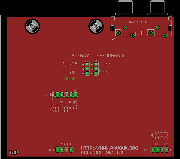
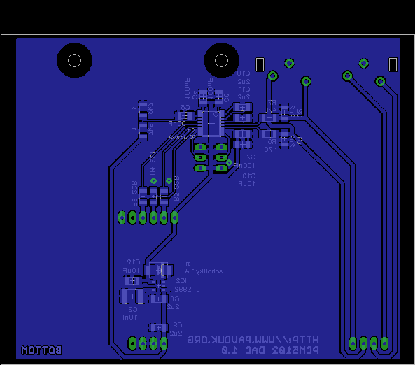
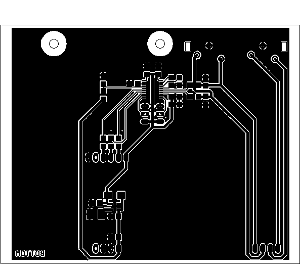
Printed circuit board is double-sided. Thanks to the simple circuit is majority of surface used for shield and is connected to the GND. On the sides absent copper layer that will not be connected to the grounded chassis. I ordered manufacturing of PCB at company Seeed Studio. Required Gerber and Excellon files can be generated in a Free version of Eagle from a materials which are provided here.
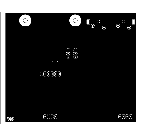
Top side view.
 Bottom side view.
Rear panel view.
Bottom side view.
Rear panel view.

Parts can be purchased for example at Farnell company. I had a little troubles to find capacitor C3 because it is a film type which is not common but it is possible to replace them with ceramic capacitor. For DAC I used PCM5102 which have only one difference from a version A that it doesn't support 1.8V logic levels.
| name | value and type | quantity |
|---|---|---|
| C1, C2 | 2n2 SMD1206 ceramic | 2x |
| C3 | 10nF SMD1812 film type | 1x |
| C4-C7 | 100nF SMD1206 ceramic | 4x |
| C8-C11 | 2u2 SMD1206 ceramic | 4x |
| C12, C13 | 10uF SMD1206 ceramic | 2x |
| D1 | Schottky 1A SMD size B | 1x |
| IC1 | PCM5102A (PCM5101A, PCM5100A) | 1x |
| IC2 | LP2992AIM5-3.3/NOPB SOT23-DBV | 1x |
| JP1, JP2 | Jumper ribbon 3 pins | 2x |
| R1 | 7k25 (7k5) SMD1206 | 1x |
| R2 | 2k75 (2k7) SMD1206 | 1x |
| R3-R5 | 22R SMD1206 | 3x |
| R6, R7 | 470 SMD1206 | 2x |
| X1, X2 | Jumper ribbon 90° 4 pins S1G4 | 2x |
| X3 | Jumper ribbon 6 pins 15mm | 1x |
| X4 | Cinch 4x socket to the PCB | 1x |
DAC works on the first power-on. It sounds very good and equal. Unfortunately is lost spatial effect and location of instruments. Also instruments with higher amount of high non-sinus frequencies we must literally seek for them. On the oscilloscope looks shape exactly that how must look output from a delta-sigma DAC with oversampling. Anyone 16 bits R-2R DAC without oversampling is better. I tried to compare output with FIR and IIR filter but I didn't see any bigger difference in quality of sound. I also noticed that while generating of signal with maximum amplitude 0dB is signal cropped/limited. Clean is about from -4dB. DAC was not disappointment but also not surprise. For great experience from a good record it will be needed other construction with R-2R DAC without oversampling.
-
 English
 Česky
Česky