
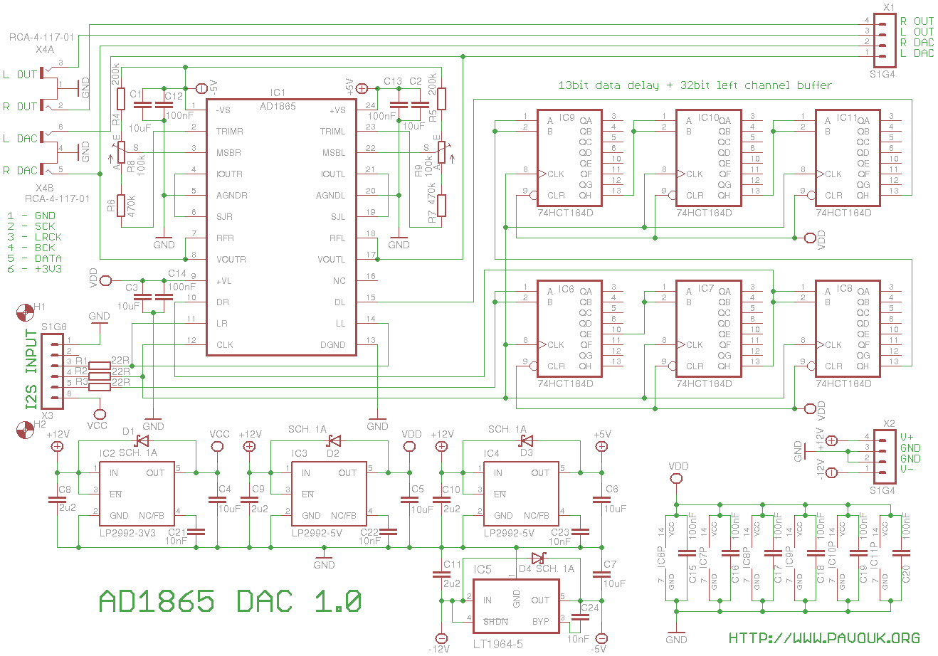
DAC with AD1865 I already built many times and I like his sound that I can't miss them now. I slightly changed circuit for fit in to the Audio system 2.0 concept.
DAC doesn't have I2S input, which is usual. It has individual data inputs for left and right channel and individual "latch" inputs which rewrites data from internal register to DAC output. Input data in I2S format (left justified) are first delayed for 13 bits thus that after shifting of 18 most significant bits to the dac register they will be written to output. For simultaneous playing of left and right channel we must delay data of left channel for 32 clock cycles (frame lenght for one channel). Result is that data for left and right channel are shifted together to the dac and they are written to the output with common latch signal. Because there doesn't exists 32bit shift-register I had two choices. Create them with help of Xilinx, but I have not experience with it or assemble them from easily available 8bit shift-registers. I wanted to avoid variant with registers train. However prototype with CMOS 64bit register CD4517 doesn't work thanks to different logic levels. On the end I had to use plenty of 74HCT164 which have 13 bits delay function and 32 bit register for left channel data.
For supplying I used for low-noise voltage regulators. Two LP2992-5V for feeding of analog and digital part of DAC, one LT1964-5V for negative analog supply of DAC and one LP2992-3V3 for supplying of input module. AD1865 works with 5V TTL logic but it also accept LVTTL same like 74HCT164 that circuit works with 3.3V logic on the I2S input.
I used analog voltage output. Output voltage is +/- 3V. on his output can be a small DC offset. On my piece I measured 6.5mV on one channel and 11.9mV on the second. Somebody recommend to use current output and use external I/V convertor from resistor or operational amplifier. For me it doesn't proved because it was more sensitive for interference.
Resistors and trimmers R4 to R9 are for precise MSB value adjustment for very weak input signal about -60dB. It can result even smaller THD+N for very weak signals. This part is optional.
First I assembled voltage regulators IC2 to IC5 and all parts around them. Next I connected board to the power supply and I checked voltages on the voltage regulator outputs if they are OK. Next I added resistors R1 to R3, shift-registers IC6 to IC11 and rest SMD capacitors. Next I assembled DAC IC1 and connectors X1 to X4. On the end I screwed distance columns for mounting of input board.
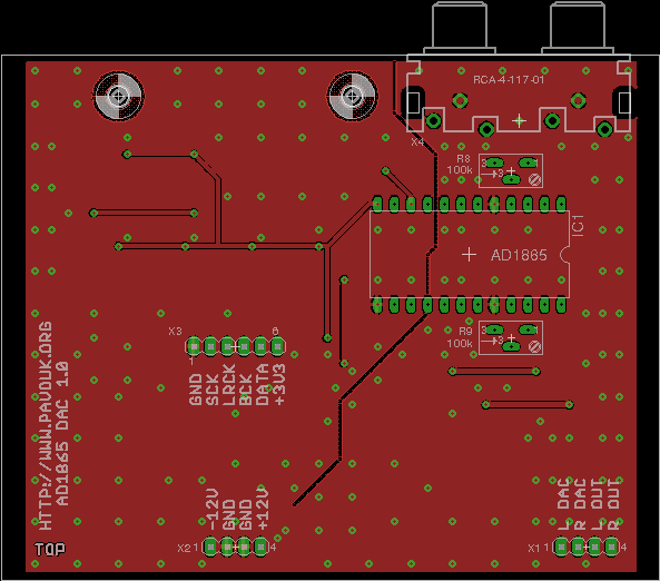
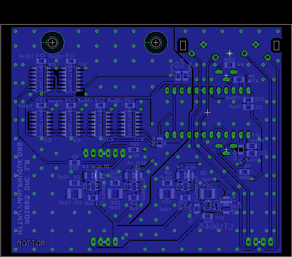
Printed circuit board is designed double-sided. Majority of his surface is ground-plane divided on analog and digital part joined at supply part. Ground plane is on many places connected with vias for better shielding. Thickness of the board could be ideally 2mm for good inserting to the hammond chassis. On the sides ground plane is missing for good electric isolation from a grounded chassis. I ordered PCB at Seeed Studio company. Required Gerber and Excellon files is possible to generate in a Free version of Eagle from a data which are available here.
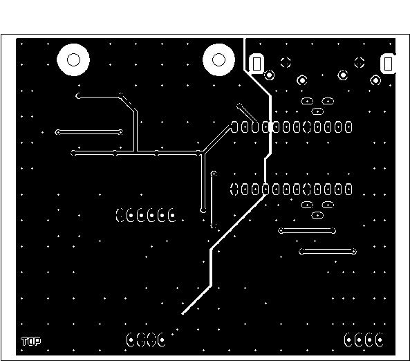
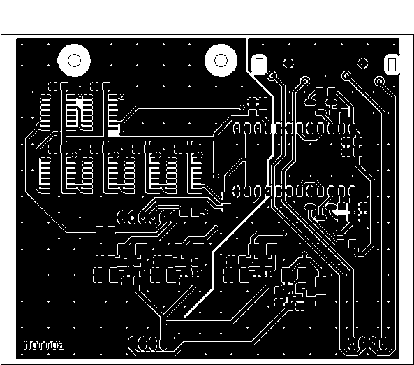
Top side view
Bottom side view
 View to the opened box

Parts can be purchased for example at Farnell company. I had a little troubles to find capacitor C21 to C24 because it is foil capacitor which is not common but it can be replaced with ceramic capacitor. DAC AD1865 is not manufactured anymore but I purchased them from EBay.
| name | value and type | quantity |
|---|---|---|
| C1-C7 | 10uF SMD1206 ceramic | 7x |
| C8-C11 | 2u2 SMD1206 ceramic | 4x |
| C12-C20 | 100nF SMD1206 ceramic | 9x |
| C21-C24 | 10nF SMD1812 foil | 4x |
| D1-D4 | Schottky 1A SMD size B | 4x |
| IC1 | AD1865N-K (AD1865N-J, AD1865N) | 1x |
| IC2 | LP2992AIM5-3.3/NOPB SOT23-DBV | 1x |
| IC3, IC4 | LP2992AIM5-5/NOPB SOT23-DBV | 2x |
| IC5 | LT1964ES5-5 | 1x |
| IC6-IC11 | 74HCT164 SMD SO14 | 6x |
| R1-R3 | 22R SMD1206 | 3x |
| R4, R5 | 200k SMD1206 | 2x |
| R6, R7 | 470k SMD1206 | 2x |
| R8, R9 | trimmer 100k multiturn 64Y | 2x |
| X1, X2 | Jumper ribbon 90° 4 pins S1G4 | 2x |
| X3 | Jumper ribbon 6 pins 15mm | 1x |
| X4 | Connector cinch 4x socket to the PCB | 1x |
I turned-up the DAC, play the music, rotate volume knob and NOTHING. Next I discovered that I had turned down volume on headphones :-) I was really nice surprised with a huge difference in a sound compared to PCM5102A. Well-known songs get a huge space and individual instruments can be now recognized. I must tell that I am really satisfied with this DAC. Again was confirmed that sound from a R-2R DACs is more interesting than from a delta-sigma DACs. Also technically bad songs are more distinguished and worse MP3s are not listenable. Quality CD records are good enough but from my CDs it is about 10% to 20%.
-
 English
 Česky
Česky