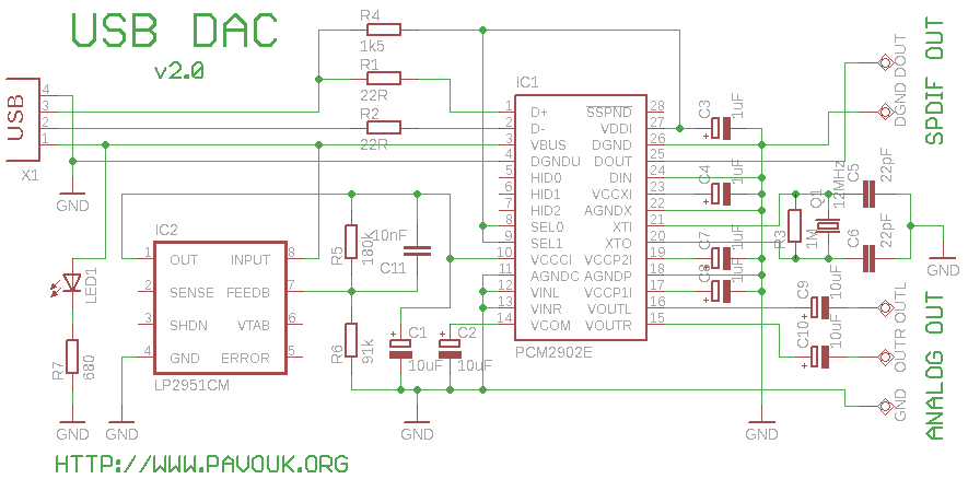
I want to build high quality preamplifier with built-in DAC from SPDIF or USB for my power amplifier Leachamp. I had available circuit PCM2902. I tried to design DAC from USB with this circuit on one-sided PCB and I was succesful.
Schematics is from datasheet of PCM2902. Circuit includes DAC and ADC, SPDIF output and input and HID part with 3 buttons for MUTE, VOL+ and VOL-. I used only DAC part. Other parts are not used. For high quality playback is needed to use external low-drop voltage stabiliser for DAC part. I used LP2951CM which was available at local store. Output voltage is set to about 3.7V with two resistors. Circuit board is designed regarding to good ground placement and separating of analog and digital ground. These ground are connected in one point at USB connector.
After drilling holes for crystal, output pads and USB connector I placed integrated circuit PCM2902, because I want space around him for soldering. I placed circuit at right place, soldered one pin on the side a next goes over all pins on second side and next same on first side. Almost all pins are now shorted. Now I take up tin with a solder wick. There must be enough flux on place for good disconnecting of shorted pins. After visual and electrical check we can make identical procedure with voltage stabiliser. Here is not too critical, because there are more space between pins. Next I placed SMD resistors, ceramic capacitors and LED. These parts I shoulder, that after placing on right place hold with nail, screwdriver or tweezer. One pin I solder with small amount of tin. If part still sits on right place, I solder second end and next I finally solder first end. Next I place tantal capacitors and crystal because they are big. On the end I solder USB connector. Circuit must work immediately after first connection to system a advertise like standard USB soundcard. For normal operating systems like Linux or Windows XP are not needed special drivers.
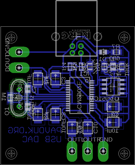
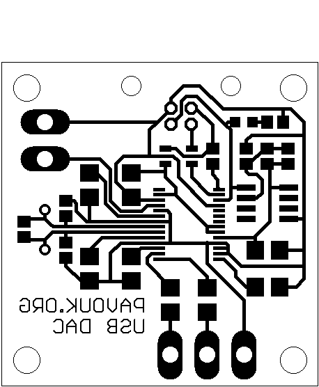
Circuit board is designed one-sided and everything beside crystal and USB connector are placed from the bottom side. Circuit board is available for free version of program Eagle, which can be free downloaded from their homepage.
 Postscript format
Eagle format
Postscript format
Eagle format


| name | value | number |
|---|---|---|
| R1, R2 | 22R SMD 0805 | 2 pcs |
| R3 | 1M SMD 0805 | 1 pc |
| R4 | 1k5 SMD 0805 | 1 pc |
| R5 | 180k SMD 0805 | 1 pc |
| R6 | 91k SMD 0805 | 1 pc |
| R7 | 680 SMD 0805 | 1 pc |
| LED1 | green LED SMD 0805 | 1 pc |
| C1, C2, C9, C10 | 10uF/35V SMD tantal | 4 pcs |
| C3, C4, C7, C8 | 1uF/35V SMD tantal | 4 pcs |
| C5, C6 | 22pF SMD 0805 ceramic | 2 pcs |
| C11 | 10nF SMD 0805 ceramic | 1 pc |
| IC1 | PCM2902E (PCM2900E) SSOP | 1 pc |
| IC2 | LP2951CM | 1 pc |
| Q1 | 12MHz crystal | 1 pc |
| X1 | USB type B connector | 1 pc |
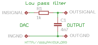 In datasheet of PCM2902 is recommended to connect Low Pass Filter to output
of DAC for filtering high frequencies above audioband which are produced
by oversampling conversion. Integrated circuit includes digital LPF
which filters frequency above 100kHz. In application notes for filter
on the manufacturer pages are recommended 1st-Order LPF (simple RC) or
2nd-Order with operation amplifiers which works like preamplifier too.
I used simple RC LPF with recommended values R 1k and C 4n7.
It's better to use roll-type capacitor instead ceramic. I didn't hear
difference in a sound between connection with filter or without it, but
with respect to other components in a audio chain it is better to use it.
For a higher cut-off frequency we can change value of capacitor to 3n3.
In datasheet of PCM2902 is recommended to connect Low Pass Filter to output
of DAC for filtering high frequencies above audioband which are produced
by oversampling conversion. Integrated circuit includes digital LPF
which filters frequency above 100kHz. In application notes for filter
on the manufacturer pages are recommended 1st-Order LPF (simple RC) or
2nd-Order with operation amplifiers which works like preamplifier too.
I used simple RC LPF with recommended values R 1k and C 4n7.
It's better to use roll-type capacitor instead ceramic. I didn't hear
difference in a sound between connection with filter or without it, but
with respect to other components in a audio chain it is better to use it.
For a higher cut-off frequency we can change value of capacitor to 3n3.
This DAC is relativelly simple for construction thanks to one-sided circuit board. Complementing is easy in amateurish conditions and his sound is very good with minimal interference. Sound is not crystally clean. Frequency band looks flat, but localization of individual instruments is a little worse. Maybe there can be enough to replace output electrolytic capacitors with roll-type, but this will require much space. I will try to build one more DAC without oversampling, if it will have sharper sound which I imagine for my amplifier.
Schematics diagram and circuit board was updated due to possibility to have digital SPDIF output. Circuit will be used as USB-SPDIF converter and will be connected to external high quality DAC.
 English
 Česky
Česky