
Today are still more used audio amplifiers in Class D. Until now I had experience only with Class A and Class AB amplifiers and I had chance to get evaluation board TPA3116D2EVM that I decided to build it in a Hammond box and add power supply to them. This miniature board can feed power 2x 50W.
Audio amplifiers in a Class D works on the principe of pulse-width modulation where audio signal is modulated on the frequency about hundred kilohertz up to few megahertz. On the output is low-pass filter which clean-up high frequencies and on his output is speaker. Thanks to that that amplifier works in a switching mode than on them is not lost almost any power and amplifier can have only miniature heatsink or no heatsink with a smaller power. Thanks to this is amplifier more economical and also much cheaper. Output of the amplifier is in a bridge mode where speaker is connected on the positive and negative output. Thanks to this there can be for same power much lower supply voltage about 24V.
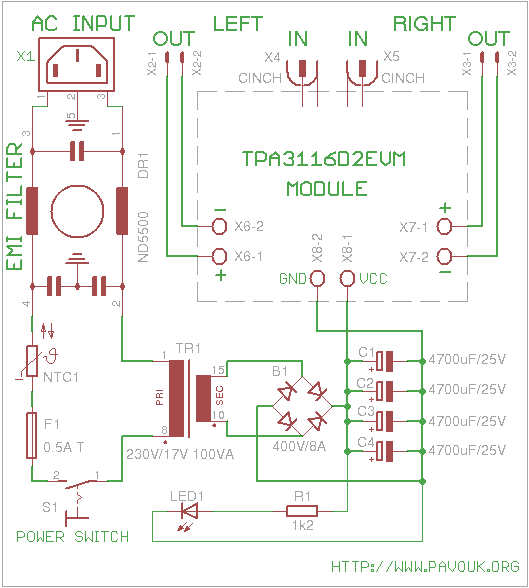
Circuit of power supply is very simple. On the input is used EMI filter which clean-up high-frequency noise from a power network and also prevent leaking of noise from a amplifier to the power cord. Via NTC thermistor which limit peak current at power-up goes phase wire to the fuse and to the switch. From them goes wire to the toroidal mains transformer.
Secondary side of transformer is connected to the bridge rectifier which output is filtered by four electrolytic capacitors 4700uF/25V. I used rectifier for current 8A. In a current peaks it can handle much more current that it probably not fail at power-up where are charged filter capacitors. Via resistor 1k2 is connected LED inside power switch. Voltage is next connected directly by wires to the EVM board. I used 100VA transformer with output voltage 17V. Without load after rectifying and filtering is output voltage about 25V. Capacitors are near their voltage limit but I hope that manufacturer has some small reserve. Amplifier chip accept voltage up to 26V.
First I arranged parts to the box and when I was happy with their positions that I marked with a pencil holes which I after that drilled. On the back and front side I glued paper sealing strips to protect plates from scratches. I arranged connectors and switch and I designed right position of holes. Afterward I doublechecked everything again and I drilled holes with a small drill. Next I enlarged holes with a bigger drill and biggest holes I refined with a rasper. Next I removed sealing strips and I finished edges of holes.
When I had all holes finished that I prepared connection wires. Because I didn't want to solder directly on the EVM module and connectors that I pressed and consequently soldered on one end pin and on the other end loop. Supply wires have instead loop on one end only tin. All ends I isolated with a shrink spaghetti. At capacitors I only bended their pins and soldered them all four together.
From a supply connector with a EMI filter goes one wire via thermistor and fuse to the power switch. From them goes one wire to the primary side of toroidal transformer. Second wire goes directly from a supply connector to the transformer. Ground wire goes under screw which hold EVM board and thanks to this is connected to the aluminium chassis. Wires from a secondary transformer winding are directly soldered to the bridge rectifier which is screwed on the base of box. On the recitifier is also directly soldered ends of pins from capacitors. Capacitors on the side are fixed with a plastic clips. Supply wires for EVM board are also soldered directly on the capacitor wires. On the end I connected all rest wires to the board and connectors and I tightened them properly.
Indication LED which is part of power switch I connected via resistor to the power branch on the capacitors.
After assembling I leaved supply wires unconnected from a EVM board. After visual check I powered-up supply and I measured output voltage. It was tightly over 25V without load. Everything looks good that after discharging of capacitors I connected EVM board and powered it up again. Everything looks OK and voltage was slightly less. I connected speakers and input signal and I checked function of amplifier.
Front side view.
 Back side.
 Detail of EVM board connection.
 Overall view.
Parts are available at common local parts shop. Except specified parts I used from my reserves wires with a cross-section 2.5mm and proper pins and loops. For isolation of end of wires I used shrink spaghetti.
| name | value and type | quantity |
|---|---|---|
| C1-C4 | 4700uF/25V electrolytic 105°C | 4x |
| B1 | Bridge rectifier 400V/8A (KBU8G) | 1x |
| NTC1 | Power thermistor NTC 10R | 1x |
| TR1 | Toroidal transformer 230V/17V 100VA | 1x |
| R1 | 1k2 | 1x |
| LED1 | Part of the switch or what you want | 1x |
| F1 | Fuse 0.5A T | 1x |
| F1' | Fuse holder PTF10 or similar | 1x |
| S1 | Power switch 250V/3A with LED | 1x |
| X1 | Power socket with EMI filter | 1x |
| X2,X3 | Double banana laboratory socket K207023 | 2x |
| BOX1 | Aluminium Hammond chassis | 1x |
| MODUL1 | TPA3116D2EVM from TI | 1x |
Amplifier surprised me at first tests with his big power, flat characteristics and totally unaudible hum or noise. But after few songs was clear that this amplifier is not suitable for HiFi. In direct compare with a Leachamp amplifier which works in a Class AB I discovered a few things. Songs lost a few space. Localisation of individual instruments is worse and complex appeal a little merged. At few songs I examined catastrophic distortion of mixture of percussion instruments. It was mainly jazz songs. It is interesting that at other songs was distortion completely unaudible. At amplifier I appreciate his miniature dimensions regarding to output power that it is handsome for carrying and occasional reproduction. In my home audio chain of course it doesn't replace my Leachamp.
 English
 Česky
Česky