This circuit is next experiment to build high quality DAC with optical input TOSLINK, electrical input S/PDIF and USB input. Both electrical inputs are galvanic separated from DAC. This circuit was thought like part of preamplifier / headphone amplifier with analog and digital inputs. I choose DAC without oversampling, which has reportedly most devoted sound.
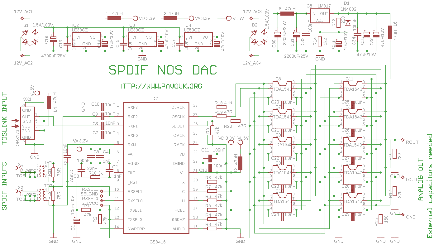
The circuit contains S/PDIF, AES signal decoder - IO CS8416. His output in I2S format is connected to the pack of parallel connected TDA1543 DACs.
Optical input is connected directly to optical receiver TORX173 which has TTL output of SPDIF signal. Electrical input is connected through pulse transformer with ratio 1:1. Recommended is pulse transformer LL1572 of Lundahl company. Next S/PDIF input from USB receiver with PCM2902 is connected also through LL1572 pulse transformer.
Feeding of S/PDIF decoder and DAC uses separated windings of transformer. Power supply for CS8416 use three low-drop stabilisers. One LE33CZ for feeding of digital part, second for analog part and one LE50CZ for logical inputs/outputs and optical receiver. Voltages are filtered by tantal capacitors and goes through filter inductors. Near chips are blocked with ceramic capacitors. DAC has separated feeding to stabiliser LM317 adjusted to 8V output. It's necessary to cool stabiliser with small piece of aluminium cooler. Every one of parallel connected DACs has his own decoupling capacitor.
Circuit CS8416 can work in hardware or software mode. In hardware mode doesn't need processor driving and he has limited number of features which are adjusted with pull-up/pull-down resistors. They are readed in the reset state. Simple reset circuit with C1/R1 causes that after powering up will be on reset logical 0 for some time and next go to logical 1 after charging capacitor. Circuit has 8 AES3/SPDIF signal inputs and internal multiplexor. In hardware mode we can switch 4 inputs with RXSEL0 and RXSEL1 pins which goes together with VCC and GND on connector. Circuit CS8416 has internal PLL which needs few external components C2, C3 and R10. Component values are from datasheet and thez are located near circuit casing. Signal from multiplexor goes to the PLL. Main clock will be synchronized to this signal. Circuit can work with sample frequency 32kHz-192kHz. In our case we are limited by capabilities of TDA1543 DAC. Decoded signal goes to the output in I2S format, which is suitable for our DAC.
TDA1543 is dual 16-bit DAC with one power supply voltage and I2S input. It is relatively old circuit which can work without oversampling. He has only 8 pins and is cheap. On the internet exists many schematics where are connected more pieces of DAC in parallel which improve bit precision of output. I use 10 pieces for parallel connection and change values of R15, R16 a R17. DAC has current outputs and R16 and R17 are simple convertors to voltage output. Outputs MUST be connected through serial connected capacitors. I use high quality foil capacitors 10uF/100V. On the internet I read, that best sound output is with power supply voltage 8V. One piece of TDA1543 has consumption about 50mA with this voltage, that with 10 pieces will be total current consuption about 0.5A and circuits will be heat. Circuit board is ready for mounting of small cooler.
First I drilled all needed holes. Next I solder CS8416 circuit, because I need a much of space around circuit for simple mounting. I soldered two corner pins and after visual check I soldered next pins. Pins was not alloy. You can too go with soldering iron and tin over all pins on one side, but this method is better with smaller parts in TSSOP package. Next I continued with soldering of smaller parts to bigger parts. SMD resistors and capacitors I first fix on the right position with my finger-nail and a little solder on one side. Next I solder second side of part and finally solder first side. It is my well-established technique, but other people uses other methods. After placing of all SMD parts and one wire connection we can settle classic parts. On the end we settle connectors on his place.
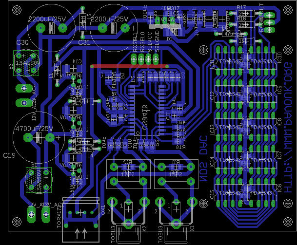
Circuit board is designed single-sided with one wire junction. SMD components are placed on bottom side and classic components are on the top. Board has drills for DAC cooler. Size of board matches maximal size of board in a free version of Eagle 4.
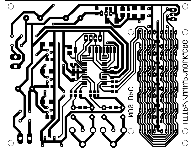 board in Postscript format
board in Eagle 4 format
board in Postscript format
board in Eagle 4 format
Circuit board is a little differ from final board. I find that in Eagle 4.16 was wrongly drawed package of stabiliser. I choosed other one and redrawed wires. Next I rotate one of power connectors for possibility to use screw terminal.


Circuit CS8416 I found at MES Praha http://www.mespraha.cz. DACs TDA1543A are available in GES electronics http://www.ges.cz. TORX173 I bought at GM Electronic http://www.gme.cz. Pulse transformer LL1572 I didn't found anywhere in our location. Maybe there can be possible to use transformer from old 10baseT ethernet card or from telco E1 card. I bought a small ferrit toroid for frequencies 2-30MHz. I wind on them about 15 turns on both input and output. Probably there will be better to have more turns, but it works. Input of CS8416 is much sensitive. Other components are commonly available.
| quantity | name | value |
|---|---|---|
| Resistors | ||
| 9x | R1-R9 | 47k SMD 0805 |
| 1x | R10 | 3k SMD 0805 |
| 2x | R11, R12 | 75R SMD 1206 |
| 1x | R13 | 220R SMD 0805 |
| 1x | R14 | 1k2 SMD 0805 |
| 3x | R18-R20 | 47R SMD 0805 |
| 1x | R15 | 150R 0.5W 1% |
| 2x | R16, R17 | 220R 0.5W 1% |
| Capacitors | ||
| 2x | C1, C33 | 10uF/10V SMD B |
| 5x | C14, C16, C18, C35, C36 | 47uF/10V SMD C |
| 2x | C2, C4 | 1nF SMD 0805 mat.C0G,NPO |
| 1x | C3 | 22nF SMD 0805 mat.X7R |
| 5x | C6-C10 | 10nF SMD 0805 |
| 8x | C5, C11-C13, C15, C17, C32, C34 | 100nF SMD 1206 |
| 10x | C20-C29 | 100nF SMD 0805 |
| 1x | C19 | 4700uF/25V electrolytic 105gr celsius |
| 2x | C30, C31 | 2200uF/25V electrolytic 105gr celsius |
| Semiconductors | ||
| 2x | B1, B2 | diode bridge 1.5A/100V circular |
| 1x | D1 | 1N4002 SMD MELF |
| 1x | IC1 | CS8416 SOIC28 |
| 2x | IC2, IC3 | LE33CZ TO92 |
| 1x | IC4 | LE50CZ TO92 |
| 1x | IC5 | LM317 TO220 |
| 10x | IC6-IC15 | TDA1543 DIL8 |
| 1x | OX1 | TORX173 |
| Inductances and transformers | ||
| 6x | L1-L6 | 47uH axial |
| 2x | TR1, TR2 | LL1572 Lundahl pulse transformer |
| 1x | _ | 230V/2x12V main supply transformer |
| Others | ||
| 2x | X1, X2 | Cinch for PCB mounting |
My DAC has problems to work. First I thought that SPDIF signal is too low. I tried to bridge pulse transformer. Next I thought that SPDIF source from computer is bad. I checked that something is generated and I tried SPDIF output from set-top-box. I tried optical input too, but everything without success. It looks like that on the I2S output is nothing generated. There should be idle mute sample signal. It looks like there are some problem with reset of circuit CS8416. I tried to reset him manually many times and I reached only that he somehow works and on output was generated nice loud noise which was muted in a pause. I tried to replace reset circuit with special 3 pin reset IO MCP120, but without success. I tried to place small resistors on signal paths between decoder and DAC (some people do this for lower interference) but still without success. Next I tried to replace SMD capacitors in PLL filter with types with recommended dielectric and nothing happen. Finally i replaced circuit CS8416 for another, but situation is same. I can not tell where I made mistake. Wiring diagram is relative simple. Circuit is used in another DACs on the internet and there works.
I fixed the problem. CM CHEANG give me a notice, that main problem is, that IO TDA1543 is not identical to TDA1543A. I couldn't find datasheet anywhere on the internet. TDA1543 use I2S data format input, but TDA1543A use EIAJ format, which I identified like "Right justified". If you use these circuits, you must switch the output data format of CS8416 with two resistors R3 to +5V and R7 to GND like in datasheet. After this DAC begins to play very nicely. After two hours there was cracking in a sound. DACs are really hot and some of them probably dies when they was running without a cooler. Don't run DACs on 8V voltage without cooler!
 English
 Česky
Česky