For transferring of digital audio between components is usually used S/PDIF (electrical) and TOSLINK (optical) interface for commercial use or AES3 for professional use. S/PDIF decoder module is intended for converting this interface to I2S interface, which is standardly used on audio DACs. I already built S/PDIF decoder with DIR9001 circuit, but in our country is available CS8416. I had troubles with resetting of this circuit in past, but now I was succesful and circuit works perfectly. CS8416 in comparison with DIR9001 support 192kHz sample frequency. It has 4 inputs instead of one. In direct comparison with older circuits CS8413/14 it has lower jitter when we use PDUR=1 settings (122ps instead 150ps). DIR9001 has jitter about 50ps.
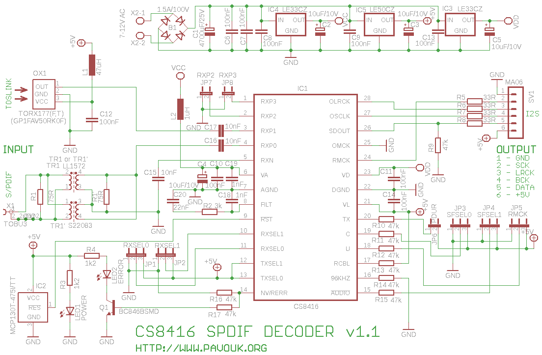
In supply section after bridge rectifier and smoothing capacitor I use LOW-DROP voltage regulators IC3, IC4 LE33CZ and IC5 LE50CZ. I used separated voltages 3.3V for analog and digital part. For inputs and outputs I choosed +5V because I needed them for optical receiver too. I used supply transformer with 9V on secondary winding. We can use more, but regulators will be hot.
CS8416 circuit may work in hardware or software mode. I choosed hardware mode with R9 resistor connected to the ground. In this mode are functions of this chip limited and settings of parameters is made with resistors 47k connected to the ground or VL. It is not necessary connect external microprocessor to this chip.
Optical receiver is TORX173 from Toshiba and his output goes to the RXP1 input of decoder. Electrical input with impedance 75R is galvanically isolated with pulse transformer TR1 and connected to the RXP0 input. Inputs RXP2 and RXP3 are wired to the special connectors JP7 and JP8 and is possible connect to them another S/PDIF sources like USB soundcard with S/PDIF output. Negative terminal RXN of symmetrical input is connected through C15 to the ground. CS8416 has bult-in RS485 receiver, that we don't need to use external and we can directly connect S/PDIF signal with +/- 1V levels or TTL.
On the FILT pin are connected PLL filter components. Their values are from datasheet and they allow right detection of signal with 32-192kHz sample frequency. Clocks and other signals are synchronized to S/PDIF input signal.
Circuit CS8416 must be resetted after power-on with external reset circuit. I choosed circuit IC2 MCP130T-475I/TT with internal pull-up resistor, because it is not part of IC1. Circuit IC2 works that, that after power-on holds RESET signal on the ground until voltage is not above 4.75 volts. After that it still holds them for about 350ms. Next signal goes to the logical one thanks to internal pull-up resistor. When voltage goes down under threshold value, that reset circuit drops RESET signal down.
Output signals GND, SCK, LRCK, BCK, DATA and +5V goes to six pin connector, which is dedicated for connection of DAC. POWER LED signaling presence of power voltage. ERROR LED lights when S/PDIF signal is not present or there are detected error. In difference to DIR9001 decoder lights when S/PDIF signal is right detected, but sound is not played. For _AUDIO LED was not space on the board. Next circuit includes few blocking capacitors and many setting jumpers with resistors which are described later.
We must place components on board from smaller to bigger. We can begin with IC1. I soldered two end pins for good fixing of circuit on the right place. I applied fluid flux on all pins for easier soldering. Next I solder all pins with soldering iron and pipe tin. Some of pins can be shorted together. I used solder wick for superfluous tin. I checked visually PCB with bright lamp. Next I continued with placing of SMD resistors, capacitors, transistor and IC2. Next I continued from upper side with wire-wraps and all other components. When we doesn't need optical input, we doesn't place OX1, C12 and L1. When we don't want electrical input, we don't place X1, R1 and TR1.
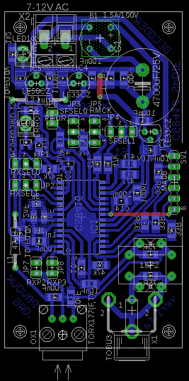
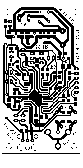
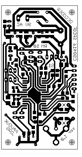
Printed circuit board is designed with only one side and two wire connections. It allows to create him in amateur conditions. Dimension of PCB, connectors and holes are identical to DIR9001 decoder, that we can replace one with another. PCB is a little complicated, but I had not troubles with assembling. Signal and power trails was designed with emphasis on low interference and influence specially on analog part which is important for low jitter.
Jumpers JP1 (RXSEL0) and JP2 (RXSEL1) are designated for choose of one input from the four RXP0-RXP3 inputs. Output data format is selected with jumpers JP3 SFSEL0 and JP4 SFSEL1. It is necessary to choose same format that supports our DAC. RMCK frequency or system clock (SCK) we select with jumper JP5 to same value that is supported by our DAC. If DAC doesn't use this signal we can select any of them. PDUR (Phase Detector Update Rate) we select with JP6. Circuit CS8416 has built-in pull-down resistor on this pin, that we short jumper only for PDUR=1. This setting is suitable for sample frequency to 96kHz because it guarantee lower jitter. It is not supported for 192kHz sample frequency. When we want to use this frequency, we must pull out jumper. Detailed description and tests are in linked application note.
| Digital input selection RXP0-RXP3 | ||
|---|---|---|
| JP2 RXSEL1 | JP1 RXSEL0 | Used input |
| 0 | 0 | RXP0 - electrical |
| 0 | 1 | RXP1 - optical |
| 1 | 0 | RXP2 - external |
| 1 | 1 | RXP3 - external |
| Data output format selection | ||
| JP4 SFSEL1 | JP3 SFSEL0 | Data output format |
| 0 | 0 | 24-bit, left-justified |
| 0 | 1 | 24-bit, I2S |
| 1 | 0 | 24-bit, right-justified |
| 1 | 1 | Direct AES3 |
| System clock selection RMCK (SCK) | ||
| JP5 RMCK | RMCK frequency | |
| 0 | 256*fs | |
| 1 | 128*fs | |
| Phase Detector Update Rate selection | ||
| JP6 PDUR | PDUR | |
| 0 | Normal | |
| 1 | Higher | |


Most of components we can get in our local store, for example GM Electronic or GES Electronic. Circuit CS8416 i bought at MES Praha company and pulse transformer PE-65612 i bought on EBay.
| name | value and type | quantity |
|---|---|---|
| R1 | 75R SMD1206 | 1x |
| R2 | 3k SMD0805 | 1x |
| R3-R4 | 1k2 SMD1206 | 2x |
| R5-R8 | 33R SMD1206 | 4x |
| R9-R17 | 47k SMD1206 | 9x |
| C1 | 4700uF/25V elektrolytic | 1x |
| C2-C5 | 10uF/10V SMD tantal size B | 4x |
| C6-C14 | 100nF SMD1206 ceramic | 9x |
| C15-C17 | 10nF SMD1206 ceramic | 3x |
| C18-C19 | 1nF SMD0805 ceramic | 2x |
| C20 | 22nF SMD0805 ceramic | 1x |
| L1 | 47uH axial | 1x |
| L2 | ferrite bead | 1x |
| IC1 | CS8416 28SOIC | 1x |
| IC2 | MCP130T-475I/TT SOT23 | 1x |
| IC3-IC4 | LE33CZ | 2x |
| IC5 | LE50CZ | 1x |
| Q1 | transistor BC846BSMD SOT23 | 1x |
| LED1 | LED green 2mA 3mm | 1x |
| LED2 | LED red 2mA 3mm | 1x |
| B1 | bridge rectifier 1.5A/100V | 1x |
| OX1 | TORX173 toshiba - PCB version 1.0 | 1x |
| OX1 | TORX177 Toshiba, GP1FAV50RK0F Sharp - pcb version 1.1 | 1x |
| SV1 | jumper ribbon 6 pins | 1x |
| JP1-JP5 | JP2E 3 pin jumper ribbon | 5x |
| JP6-JP8 | JP1E 2 pin jumper ribbon | 3x |
| TR1 | LL1572 or S22083 or PE-65612 or DA102C | 1x |
| X1 | cinch female to PCB TOBU3 | 1x |
| X2 | frame terminal AK300/2 | 1x |
Board works perfectly on first connection. This S/PDIF decoder we can use like alternative to DIR9001 based decoder maybe because it will be easily available in your country or when you want to use 192kHz sample frequency.
 English
 Česky
Česky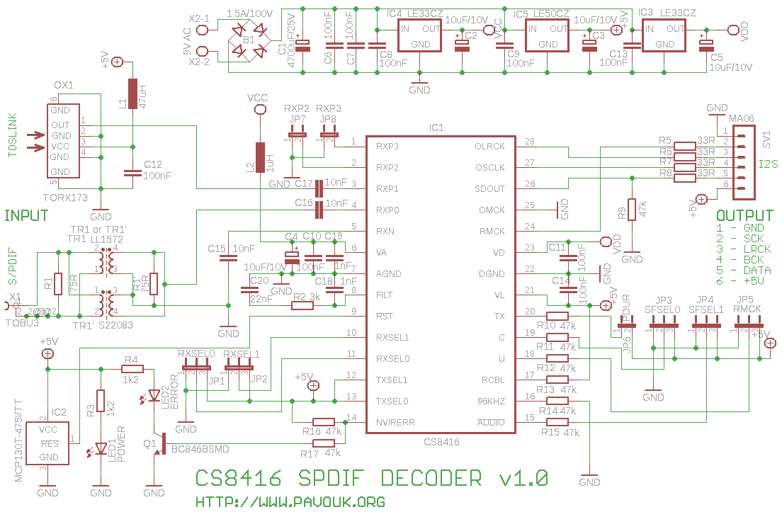